Usb-compatible lithium-ion battery charger with thermal regulation
CONSONANCE Lithium Ion Battery Charger for Solar-Powered Systems General Description: Features:
The CN3083 is a complete constant-current /constant
On-chip 8-bit ADC can adjust charging current
voltage linear charger for single cell Li-ion and Li
automatically based on the output capability of
Polymer rechargeable batteries. The device contains
an on-chip power MOSFET and eliminates the need
for the external sense resistor and blocking diode. An
on-chip 8-bit ADC can adjust charging current
No external Blocking Diode or Current Sense
automatically based on the output capability of input
power supply, so CN3083 is ideally suited for solar
Preset 4.2V Regulation Voltage with 1%
powered system. Furthermore, the CN3083 is
Accuracy, adjustable with an external resistor
specifically designed to work within USB power
Precharge Conditioning for Reviving Deeply
specifications. Thermal feedback regulates the
charge current to limit the die temperature during
Dissipation During Initial Stage of Charge
high power operation or high ambient temperature.
Continuous Programmable Charge Current Up
The regulation voltage is internally fixed at 4.2V
with 1% accuracy, it can also be adjusted with an
Constant-Current/Constant-Voltage Operation
external resistor. The charge current can be
with Thermal Regulation to Maximize Charge
programmed externally with a single resistor. When
Automatic Low-Power Sleep Mode When Input
automatically enters a low power sleep mode ,
dropping the battery drain current to less than 3uA.
Status Indication for LEDs or uP Interface
Other features include undervoltage lockout,
automatic recharge, battery temperature sensing and
The CN3083 is available in a thermally enhanced
Applications: Pin Assignment
Solar Powered System Digital Still Cameras
CONSONANCE Typical Application Circuit
Figure 1 Typical Application Circuit(Constant Voltage Level 4.2V)
Figure 2 Application Circuit(Adjust Constant Voltage Level with Rx)
In Figure 2, the BAT pin’s voltage in constant voltage mode is given by the following equation:
Block Diagram Pin Description Function Description Temperature Sense Input. Connecting TEMP pin to NTC thermistor’s
output in Lithium ion battery pack. If TEMP pin’s voltage is below 46% of
input supply voltage VIN for more than 0.15S, this means that battery’s
temperature is too high or too low, charging is suspended. If TEMP’s voltage
level is above 46% of input supply voltage for more than 0.15S, battery fault
state is released, and charging will resume.
The temperature sense function can be disabled by grounding the TEMP pin.
Constant Charge Current Setting and Charge Current Monitor Pin. The
charge current is set by connecting a resistor RISET from this pin to GND. When in precharge mode, the ISET pin’s voltage is regulated to 0.2V. When in
constant charge current mode, the ISET pin’s voltage is regulated to 2V. In all
modes during charging, the voltage on ISET pin can be used to measure the
Ground Terminal. Positive Input Supply Voltage. VIN is the power supply to the internal circuit.
When VIN drops to within 40mv of the BAT pin voltage, CN3083 enters low power sleep mode, dropping BAT pin’s current to less than 3uA.
Battery Connection Pin. Connect the positive terminal of the battery to BAT
pin. BAT pin draws less than 3uA current in chip disable mode or in sleep
mode. BAT pin provides charge current to the battery and provides regulation
Open-Drain Charge termination Status Output. In charge termination
status, OK is pulled low by an internal switch; Otherwise OK pin is in high
Open Drain Charge Status Output. When the battery is being charged, the
CH pin is pulled low by an internal switch, otherwise CH pin is in high
Battery Voltage Kevin Sense Input. This Pin can Kelvin sense the battery
voltage; Also the regulation voltage in constant voltage mode can be adjusted
by connecting an external resistor between FB pin and BAT pin.
Absolute Maximum Ratings
All Terminal Voltage……………-0.3V to 6.5V Maximum Junction Temperature….150℃
BAT Short-Circuit Duration……….Continuous Operating Temperature….-40℃ to 85℃
Storage Temperature….-65℃ to 150℃ Thermal Resistance (SOP8)………….TBD
Lead Temperature(Soldering)…….300℃
Stresses beyond those listed under ‘Absolute Maximum Ratings’ may cause permanent damage to the device. These are stress ratings only and functional operation of the device at these or any other conditions above those indicated in the operational sections of the specifications is not implied. Exposure to Absolute Maximum Rating Conditions for extended periods may affect Electrical Characteristics
(VIN=5V, TA=-40℃ to 85℃, Typical Values are measured at TA=25℃,unless otherwise noted)
Parameters Symbol Conditions Min Typ Max Precharge Threshold Charge Termination Threshold Recharge Threshold Sleep Mode Detailed Description
The CN3083 is a linear battery charger designed primarily for charging single cell lithium-ion or
lithium-polymer batteries. Featuring an internal P-channel power MOSFET, the charger uses a
constant-current/constant-voltage to charge the batteries. Continuous charge current can be programmed up to
600mA with an external resistor. No blocking diode or sense resistor is required. The on-chip 8-bit ADC can
adjust charging current automatically based on the output capability of input power supply, so CN3083 is ideally
suited for the solar-powered systems, or the applications that need to charge lithium-ion battery or lithium
polymer battery with an input power supply whose output capability is limited. The open-drain output OK and
CH indicates the charger’s status. The internal thermal regulation circuit reduces the programmed charge current
if the die temperature attempts to rise above a preset value of approximately 115℃. This feature protects the
CN3083 from excessive temperature, and allows the user to push the limits of the power handling capability of a
given circuit board without risk of damaging the CN3083 or the external components. Another benefit of
adopting thermal regulation is that charge current can be set according to typical, not worst-case, ambient
temperatures for a given application with the assurance that the charger will automatically reduce the current in
The charge cycle begins when the voltage at the VIN pin rises above the UVLO level, a current set resistor is connected from the ISET pin to ground. The CH pin outputs a logic low to indicate that the charge cycle is
ongoing. At the beginning of the charge cycle, if the voltage at FB pin is below 3V, the charger is in precharge
mode to bring the cell voltage up to a safe level for charging. The charger goes into the fast charge
constant-current mode once the voltage on the FB pin rises above 3V. In constant current mode, the charge
current is set by RISET. When the battery approaches the regulation voltage, the charge current begins to decrease as the CN3083 enters the constant-voltage mode. When the current drops to charge termination threshold, the
charge cycle is terminated, OK is pulled low by an internal switch and CH pin assumes a high impedance state to
indicate that the charge cycle is terminated. The charge termination threshold is 10% of the current in constant
current mode. To restart the charge cycle, just remove the input voltage and reapply it. The charge cycle can also
be automatically restarted if the FB pin voltage falls below the recharge threshold. The on-chip reference voltage,
error amplifier and the resistor divider provide regulation voltage with 1% accuracy which can meet the
requirement of lithium-ion and lithium polymer batteries. When the input voltage is not present, the charger goes
into a sleep mode, dropping battery drain current to less than 3uA. This greatly reduces the current drain on the
The charging profile is shown in the following figure:
Application Information Undervoltage Lockout (UVLO) An internal undervoltage lockout circuit monitors the input voltage and keeps the charger in shutdown mode
until VIN rises above the undervoltage lockout voltage. The UVLO circuit has a built-in hysteresis of 0.1V. Sleep mode
There is an on-chip sleep comparator. The comparator keeps the charger in sleep mode if VIN falls below sleep mode threshold(VBAT+40mv). Once in sleep mode, the charger will not come out of sleep mode until VIN rises 90mv above the battery voltage.
Precharge mode At the beginning of a charge cycle, if the battery voltage is below 3V, the charger goes into precharge mode ,
and the charge current is 10% of fast charge current in constant current mode.
Charging Current limited by the Output capability of Input Power Supply If the output capability of input power supply is less than the charging current set by the resistor at ISET pin,
then the on-chip 8-bit ADC will begin to function to adjust the charging current based on the output capability
of input power supply. In this case, the charging current may be less than the value set by the resistor at ISET
pin, but it is maximized to the output capability of input power supply on the condition that the input voltage at
VIN pin is no less than 4.35V, which is the minimum operating voltage of CN3083. So the charging current can
be set according to the maximum output capability of input power supply, not the worst case.
Adjusting the regulation voltage in constant voltage mode The regulation voltage in constant voltage mode can be adjusted by an external resistor connecting between FB
Figure 5 Adjusting Regulation Voltage in Constant Voltage Mode
In Figure 5, the regulation voltage in constant voltage mode will be given by the following equation:
Vbat = 4.2+3.04×10⁻⁶×Rx Where, Vbat is in volt Rx is in ohm Programming Charge Current The formula for the battery charge current in constant current mode is:
ICH is the charge current in ampere RISET is the total resistance from the ISET pin to ground in ohm
For example, if 500mA charge current is required, calculate:
For best stability over temperature and time, 1% metal film resistors are recommended. If the charger is in
constant-temperature or constant voltage mode, the charge current can be monitored by measuring the ISET pin
voltage, and the charge current is calculated as the following equation:
Combine Two Power Inputs Although the CN3083 allows charging from a solar power supply, a wall adapter or a USB port can also be used
to charge Li-Ion/Li-polymer batteries. Figure 6 shows an example of how to combine 2 power inputs. A
P-channel MOSFET, M1, is used to prevent back conducting into the 2nd power supply when the 1st power
supply is present and Schottky diode, D1, is used to prevent 2nd power supply loss through the 1kΩ pull-down
Figure 6 Combining 2 Input Power Supply
Battery Temperature Sense To prevent the damage caused by the very high or very low temperature done to the battery pack, the CN3083
continuously senses battery pack temperature by measuring the voltage at TEMP pin.
If VTEMP<(46%×VIN) for 0.15 seconds, it indicates that the battery temperature is too high or too low and the charge cycle is suspended. If VTEMP>(46%×VIN) for 0.15 seconds, the charge cycle resumes. The battery temperature sense function can be disabled by connecting TEMP pin to GND.
Recharge After a charge cycle has terminated, if the battery voltage drops below the recharge threshold of 4.1V, a new Constant-Current/Constant-Voltage/Constant-Temperature The CN3083 use a unique architecture to charge a battery in a constant-current, constant-voltage, constant
temperature fashion as shown in Figure 3. Amplifiers Iamp, Vamp, and Tamp are used in three separate
feedback loops to force the charger into constant-current, constant-voltage, or constant-temperature mode,
respectively. In constant current mode the charge current delivered to the battery equal to 1800V/RISET. If the power dissipation of the CN3083 results in the junction temperature approaching 115℃, the amplifier Tamp will
begin decreasing the charge current to limit the die temperature to approximately 115℃. As the battery voltage
rises, the CN3083 either returns to constant-current mode or it enters constant voltage mode straight from
Open-Drain Status Outputs The CN3083 have 2 open-drain status outputs: OK and CK. CH is pulled low when the charger is in charging
status, otherwise CH becomes high impedance. OK is pulled low if the charger is in charge termination status,
When the battery is not present, the charger charges the output capacitor to the regulation voltage quickly, then
the BAT pin’s voltage decays slowly to recharge threshold because of low leakage current at BAT pin, which
results in a 100mv ripple waveform at BAT pin, in the meantime, CH pin outputs a pulse to indicate that the
battery’s absence. The pulse’s frequency is around 10Hz when a 4.7uF output capacitor is used.
The open drain status output that is not used should be tied to ground.
VIN Bypass Capacitor CIN Many types of capacitors can be used for input bypassing, CIN is typically a 22uF capacitor. For the consideration of the bypass capacitor, please refer to the Application Note AN102 from our website. Stability Typically a 4.7uF capacitor from BAT pin to GND is required to stabilize the feedback loop.
In constant current mode, the stability is also affected by the impedance at the ISET pin . With no additional
capacitance on the ISET pin, the loop is stable with current set resistors values as high as 50KΩ. However,
additional capacitance on ISET pin reduces the maximum allowed current set resistor. The pole frequency at
ISET pin should be kept above 200KHz. Therefore, if ISET pin is loaded with a capacitance C, the following
equation should be used to calculate the maximum resistance value for RISET:
In order to measure average charge current or isolate capacitive load from ISET pin, a simple RC filter can be
Figure 7 Isolating Capacitive Load on ISET Pin
Board Layout Considerations
1. RISET at ISET pin should be as close to CN3083 as possible, also the parasitic capacitance at ISET pin
2. The capacitance at VIN pin and BAT pin should be as close to CN3083 as possible.
3. During charging, CN3083’s temperature may be high, the NTC thermistor should be placed far enough to
CN3083 so that the thermistor can reflect the battery’s temperature correctly.
4. It is very important to use a good thermal PC board layout to maximize charging current. The thermal path
for the heat generated by the IC is from the die to the copper lead frame through the package lead(especially
the ground lead) to the PC board copper, the PC board copper is the heat sink. The footprint copper pads
should be as wide as possible and expand out to larger copper areas to spread and dissipate the heat to the
surrounding ambient. Feedthrough vias to inner or backside copper layers are also useful in improving the
overall thermal performance of the charger. Other heat sources on the board, not related to the charger,
must also be considered when designing a PC board layout because they will affect overall temperature rise
The ability to deliver maximum charge current under all conditions require that the exposed metal pad on
the back side of the CN3083 package be soldered to the PC board ground. Failure to make the thermal
contact between the exposed pad on the backside of the package and the copper board will result in larger
Package Information Consonance does not assume any responsibility for use of any circuitry described. Consonance reserves the right to change the circuitry and specifications without notice at any time.
Garlic (allicin) - Very effective antiviral. Best if fresh (raw) and crushed. Must be consumed within 1 hour of crushing. Dosage is initially 2 to 3 cloves per day but later reduce until no body odour occurs. No toxic effects noted. (Pubmed PMID 9049657) Vitamin C - Boosts the immune system and is an antiviral by blocking the enzyme neuraminadase. Viruses need neuraminadase to reproduce.
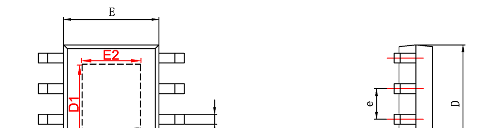
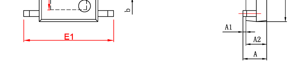
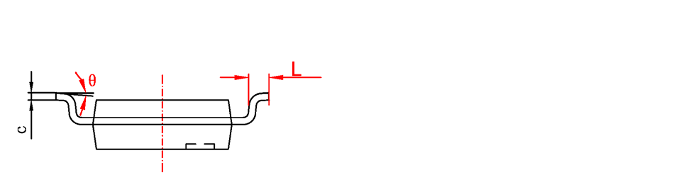
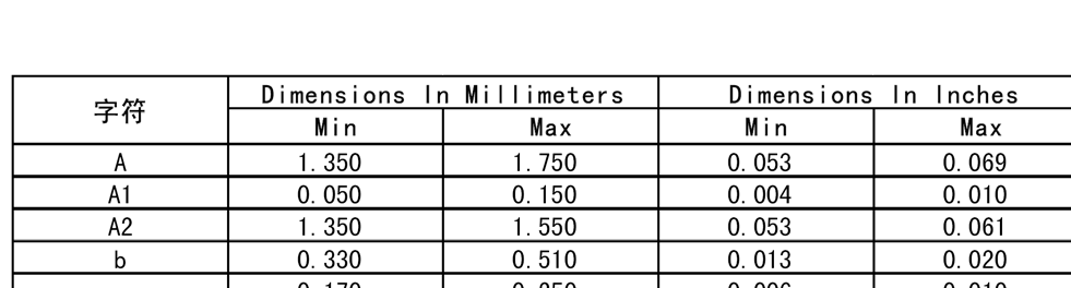
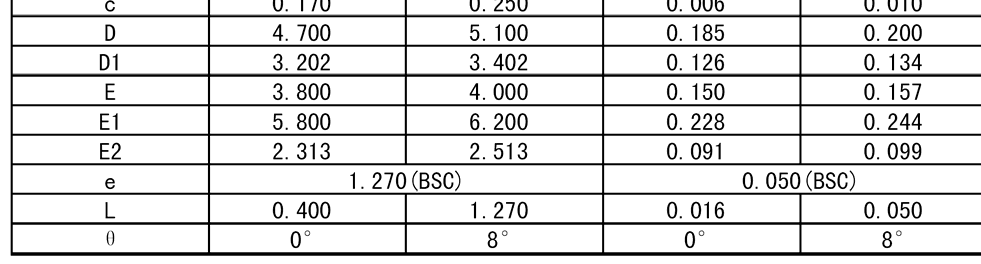 Package Information